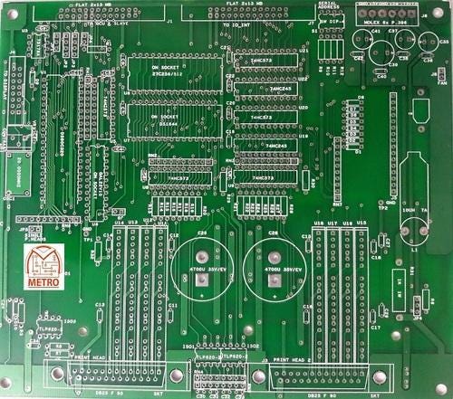
Printed circuit boards evolved from electric connection structures that had been developed inside the 1850s. Metal strips or rods have been in the beginning used to connect huge electric powered components hooked up on wood bases. In time the metallic strips have been changed via wires linked to screw terminals, and timber bases have been changed by means of steel chassis. But smaller and greater compact designs had been wished because of the accelerated working wishes of the goods that used circuit boards. In 1925, Charles Ducas of the USA submitted a patent software for a technique of making an electrical path without delay on an insulated floor by using printing through a stencil with electrically conductive inks. This technique gave beginning to the name “published wiring” or “published circuit.”
In the 1943, Paul Eisler of the UK patented a way of etching the conductive sample, or circuits, on a layer of copper foil bonded to a pitcher-strengthened, non-conductive base. Widespread use of Eisler’s method did not come until the Nineteen Fifties when the transistor turned into delivered for commercial use. Up to that factor, the scale of vacuum tubes and different additives have been so massive that the traditional mounting and wiring methods had been all that turned into wished. With the advent of transistors, but, the components became very small, and producers became to revealed circuit forums to lessen the overall length of the digital bundle.
Design
There is no such issue as a fashionable revealed circuit board. Each board has a completely unique function for a selected product and need to be designed to carry out that characteristic within the area allocated. Board designers use computer-aided design structures with unique software program to format the circuit sample on the board. The areas among electrical carrying out paths are frequently zero.04 inches (1.0 mm) or smaller. The vicinity of the holes for factor leads or touch points are also laid out, and this statistics is translated into instructions for a pc numerical controlled drilling device or for the automated solder paster used inside the manufacturing procedure.
Once the circuit sample is laid out, a negative picture, or masks, is outlined out at actual size on a clean plastic sheet. With a terrible picture, the areas that are not part of the circuit sample are shown in black and the circuit pattern is shown as clear.
Raw Materials
The substrate maximum generally used in revealed circuit forums is a pitcher fiber bolstered (fiberglass) epoxy resin with a copper foil bonded on to 1 or both sides. PCB made from paper reinforced phenolic resin with a bonded copper foil are much less steeply-priced and are frequently used in family electric gadgets.

The revealed circuits are made from copper, that is both plated or etched away at the surface of the substrate to leave the pattern favored. (See “additive” and “subtractive” strategies defined in step 3 underneath The Manufacturing Process). The copper circuits are coated with a layer of tin-result in prevent oxidation. Contact arms are plated with tin-lead, then nickel, and finally gold for great conductivity.
